.
Step-by-step instructions for the extraction of CO2 from carbonates for stable isotope analysis
 |
|
The general steps are:
- Preparing samples in reaction vessels
- Preparing cut-off tubes
- Preparing vacuum line
- Evacuating and degassing the samples and acid
- Reacting the samples
- Extraction of the gas
- Preparing the line for a new set of extractions
Note: You will need to prepare phosphoric acid before proceeding.
Preparing samples in reaction vessels:
1.
Fold a piece of c. 2 x 3" weighing paper so that 1/3 of the paper is oriented
90 degrees to the other 2/3 of the paper. Place the paper on the scale
and zero (tare) the scale.
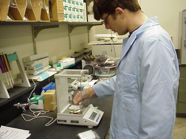 Weighing
the sample powder on a balance
Weighing
the sample powder on a balance
2. Add approximately 10 to 20 mg of the sample powder on the scale; record the weight.
3.
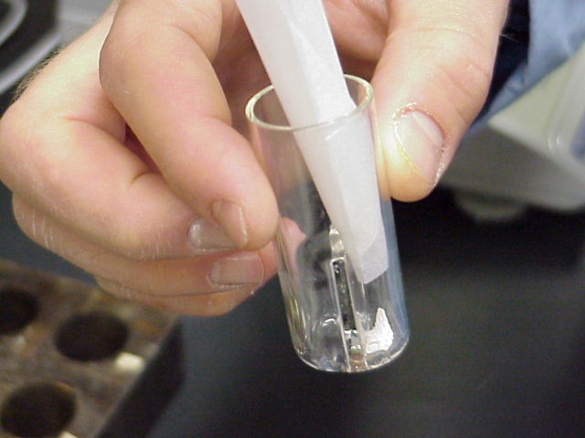
Fold another piece of c. 4 x 4" weighing paper into a funnel (tube) that
can be fit into one-half of the sample vessel. Pour the sample through
the paper funnel into one side of the partitioned sample vessel.
 |
 |
4. Repeat steps 1 through 3 for all samples and standards (analyze one standard with approximately 5 samples).
5.
Add approximately 2 to 3 ml of 100% phosphoric
acid with an intermediate size disposable dropper (68 mm) to the other
partitioned chamber of each reaction vessel. Make sure not to drip any
acid on the sample. Drips can be minimized by only inserting the tip of
the dropper in the acid rather than a large portion of the dropper.
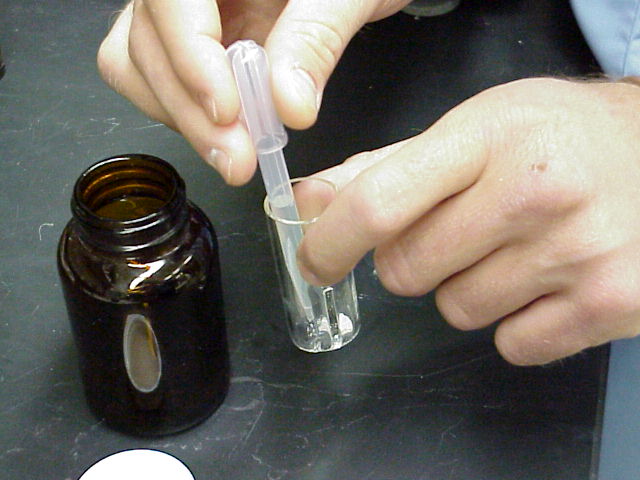 |
Placing acid in sample vial. Note divider in vial between sample powder and acid. |
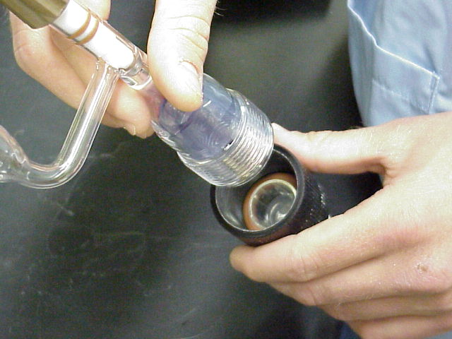
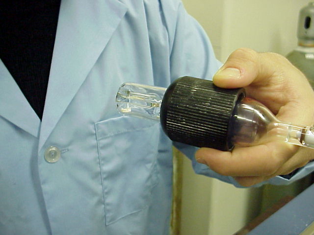
6.
Put an O-ring on each glass sample vessel. Make sure the glass and O-rings
are free of dirt, fibers, or other debris (these will prevent a good vacuum
from forming). Put the sample vessel into the screw cap and then screw
onto the glass segment with the valve. Hand tighten the screw cap firmly
in order to insure a tight fit between the O-ring and the glass.
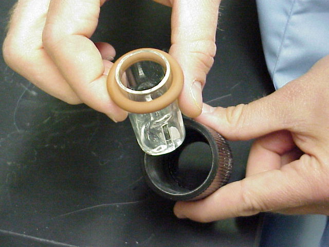 |
Sample vessel with O-ring in place and screw cap underneath. |
 |
Sample vessel with O-ring placed in screw cap and about to be screwed onto upper part of sample chamber. |
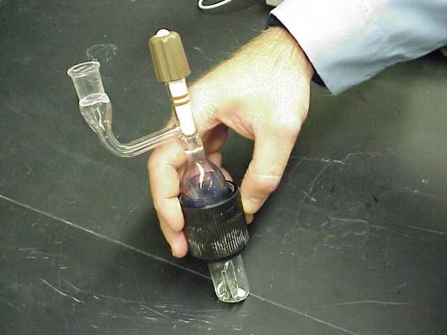 |
Assembled sample chamber. |
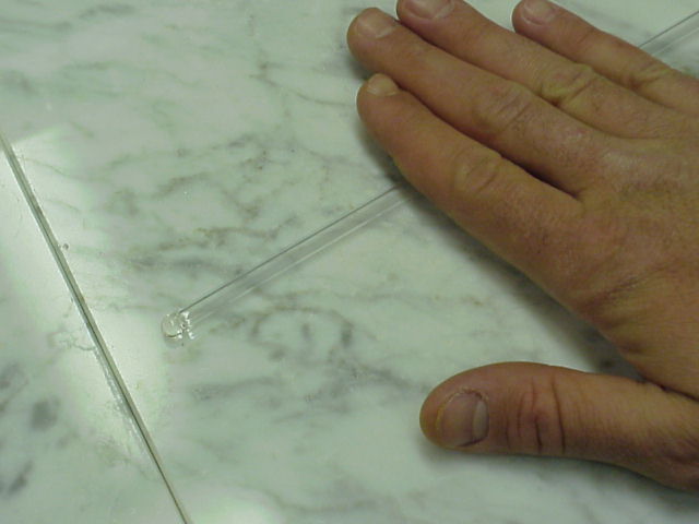
1. Buy 6mm outer diameter Pyrex glass tubing. This tubing can be bought in 25 lb. bundles.
2. Measure tubing into c. 15 to 18 cm long segments. Score (scratch) the tubing with a tungsten carbide tool. (These tube cutters can be bought from most companies selling scientific glassware.) Wet the scratch mark and gently break the tubing. If properly scored, the glass will fracture cleanly at the scratch mark. Repeat the procedure until you have enough tubes for your analyses. We generally make enough tubes at one time to last approximately 10 sets of analyses.
3.
Heat one end of the 15 cm long glass tube in a flame burning natural gas
and oxygen. Make sure to wear the proper eye protection when using the
torch (these filters out the Na-generated orange flame). Turn the tubing
in the flame while it is heating. The tube will start to melt and collapse
in on itself. Keep melting the tubing until approximately 4 to 5 mm of
the tube has melted and formed a molten glass ball. Immediately remove
from the flame and roll the tubing on a graphite or ceramic plate in order
to make the tube cylindrical its entire length. Inspect the closed end
of the tube in the light in order to insure that no tiny tubule connects
the interior of the tube to the outer surface. Such a tubule can be very
difficult to see -- it frequently appears as a small hair-thin line extending
from the interior to the exterior of the glass. If present, the tubule
will prevent you from obtaining a good vacuum.
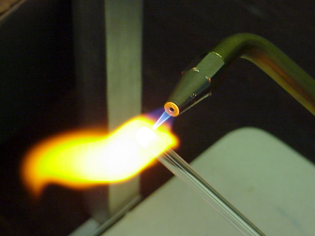 |
Using a blow torch to seal off one end of the sample glass tube. |
 |
The sealed sample tube is rolled on a flat surface to round off the end. |
 |
MPEG movie showing
how the pyrex tubing is sealed with the torch and the end is rounded off.
(WARNING: 468 Kb !) |
1. If the vacuum pump is not already running, then it should be turned on at this time. Most laboratories leave the vacuum pump running for months at a time if the extraction line is being used frequently.
2. Valve 3 should be closed and valves 2 and 4 should be open.
3.
Add a little grease to the glass fittings of the sample vessels and connect
the vessels to the vacuum line. Use rubber bands to keep the vessels from
falling off the line. The valves on each sample vessel should be open.
 |
Grease being dabbed onto the connection between the sample vessel and the extraction line. |
4.
Add the cut-off tubes to each line. Make sure the O-rings and glass are
free of dirt, fiber, and other debris. Hand tighten the screw caps.
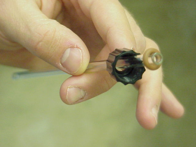 |
The CO2 sample tube (see above) with O-ring attached and screw cap slid on. |
 |
Sample tube with O-ring and screw cap ready to be placed onto end of the extraction line. |
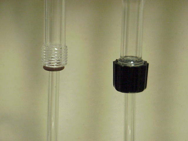 |
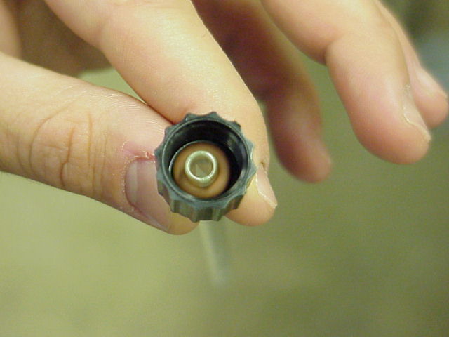
Two sample tubes attached to extraction line. Screw cap has been removed from left tube to show how the vacuum can hold the tube with O-ring in place. |
5.
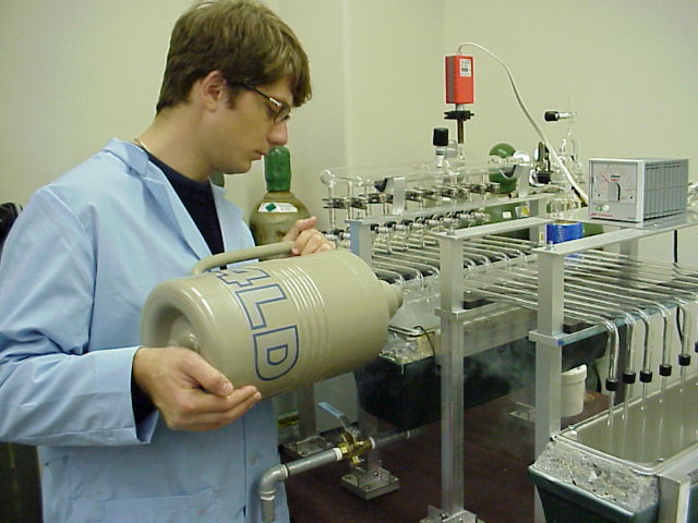
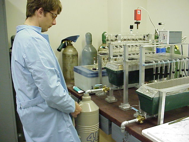
Add liquid nitrogen to the vacuum line cold trap.
 |
Drawing liquid nitrogen from supply tank into dewar |
 |
Pouring liquid nitrogen into tubs of U-shaped section of extraction line |
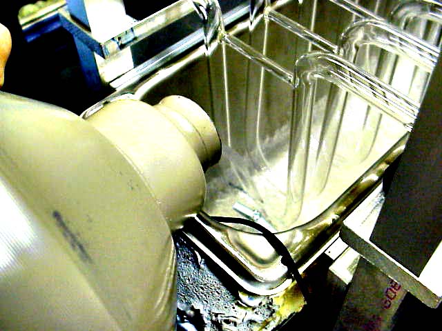 |
Close-up of U-shaped tubes and tub being filled with liquid nitrogen. |
Evacuating and degassing the samples and acid:
1. Valves 1, 2, and 4 should be open. Slowly open valve 3.
2. Rotate gently the samples in order to spread evenly the vacuum grease on the glass connections and get a good vacuum seal.
3. Turn on the pressure gauge. The pressure should quickly drop to c. 10-1 mbar, and then more slowly decrease to c. 10^-2 mbar. (The pressure will not go much lower until the acid has degassed most of its water and other gases.)
4. Check for large leaks by closing valves 2 and waiting one minute. Then open and close each valve 2 (one at a time) and monitor the gas pressure (valves 1 and 3 are open). If a line has a leak, it will have an anomalously high gas pressure relative to the other lines. Check all the lines. If a line has a leak, then open valve 2 and close valve 1. If the pressure goes down, then the leak is around the O-ring of the sample chamber. If the pressure does not go down, then the leak is either in the glass connection between the sample chamber and line, or in the cut-off tube (either in the bottom part of the tube or around the O-ring). Clean both connections, check the cut-off tube to make sure there is no tubule at its sealed end, regrease if necessary, and reconnect the line. The leak should be resolved. Open all valves 1, 2, and 3. Insure the vacuum is good.
5. Refill the waste cold trap with liquid nitrogen so that it will remain cold overnight.
6. Set the water bath temperature to 50 degrees C for overnight degassing of the samples. Make sure the water level is c. 5 cm above the sample powder and acid. (If available, use distilled water to fill the bath).
7. Turn off the pressure gauge.
8. Prior to leaving the lab for the evening, make sure the valves of all natural gas and oxygen lines are closed and make sure all furnaces are turned off.
Next morning; evacuating and degassing the samples and acid:
1. Turn on the pressure gauge and check the vacuum to insure there was no significant leak that developed overnight.
2. Refill the waste trap with liquid nitrogen.
3. If everything is ok, the pressure should be at c. 5 x 10^-3 mbar.
4. Now check for small leaks by closing all the valves 2. Wait a minute or so, and then open valve 2 on the first sample vessel and observe the gas pressure. Close valve 2 and repeat the procedure for all the vessels. If there are no leaks, then all the lines should have approximately the same gas pressure. If the pressure in each line is higher than c. 5 x 10^-3 mbar, then water is still degassing from the acid. This is not too important as long as there is not too much water. The analysis can continue since the water will be separated from the CO2 gas during the extraction process. If a line has an anomalously high pressure, then gently rotate the glass connection of the vessel and gently tighten the screw cap on the cut-off tube. Hopefully, this will take care of the minor leak.
5. Open all the valves 2 in order to maintain good vacuum.
1. Close valves 1. Close valve 3. Valves 2 are kept open.
2.
Gently remove the first sample vessel. (DO NOT pull down on the glass line;
rather, hold stationary the upper part of the connection with one hand
and gently pull down the lower part of the glass connection with the other
hand. The first sample chamber will be hardest to remove because the lines
will still be evacuated; however, after the first one is removed, the subsequent
chambers will be easy to remove.) Turn sample vessel sideways until the
acid spills into the other side vessel containing the rock powder. Do not
tilt the vessel too far because the acid should not leave the cylindrical
part of the glass vessel. If it does, then it will spill onto the O-ring
and potentially cause the vessel to loose vacuum (the acid can adversely
affect the grease on the O-ring). Turn the vessel upright and re-attach
to the glass line with a rubber band. Repeat the process for all the sample
vessels.
 |
Sample vessel being turned on its side to allow phosphoric acid to mix with sample powder. |
 |
Sample powder and acid combined. Note reaction taking place. |
|
MPEG movie showing how vessel is removed from line
and acid is mixed with sample. (It may actually take a bit longer for the
acid to move over to the opposite side of the sample vessel.)
(WARNING: 1.05 Mb file !) |
3. Wait several hours for the acid to react completely with the sample. (If the samples contain both calcite and dolomite, it is possible to do separate analyses for these two phases by extracting the gas from the sample vessels at two different times. The calcite reacts quickly relative to dolomite; therefore, the calcite-liberated CO2 can be extracted prior to significant reaction of the dolomite with the acid.)
1. Fill the waste trap container with the liquid nitrogen (LN).
2. Make sure there is a good vacuum (c. 5 x 10^-3 mbar).
3. Close gently the ball valves on the cooling trays under the glass U-tubes and cut-off tubes. (We also loosely place small rubber stoppers in the discharge holes of the cooling trays in order to minimize the bubbling cause d by evaporation of the LN in the non-insulated discharge tube.)
4. Close valves 2 for all the lines.
5. Add LN to the first cooling tray until the liquid touches the bottom of all the glass lines.
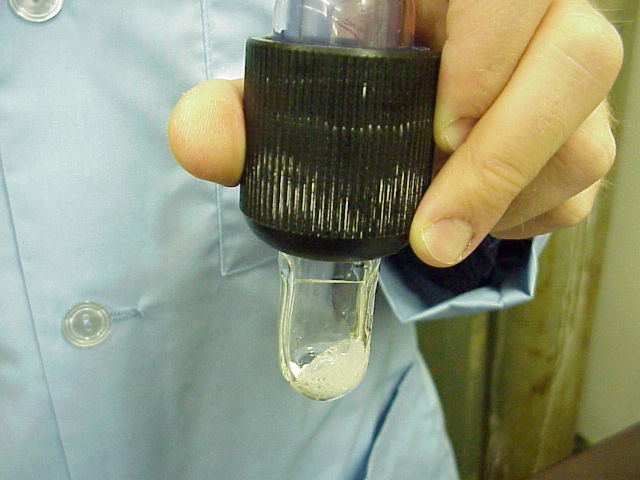
6.
Open valve 1 for each sample vessels. You should see a white precipitate
(CO2 and H2O) form on the inside
of each glass line just above the LN.
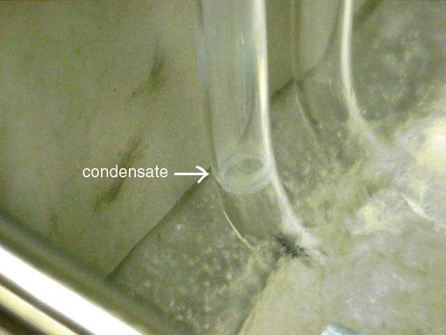 |
Section of U-tube partly immersed in liquid nitrogen. White condensate ring forms just above level of liquid nitrogen. |
7. After 1 minute, add more LN into the first cooling tray so that the height of the LN is 2 to 3 cm higher. Wait c. 10 minutes in order to insure complete condensation of all CO2 gas.
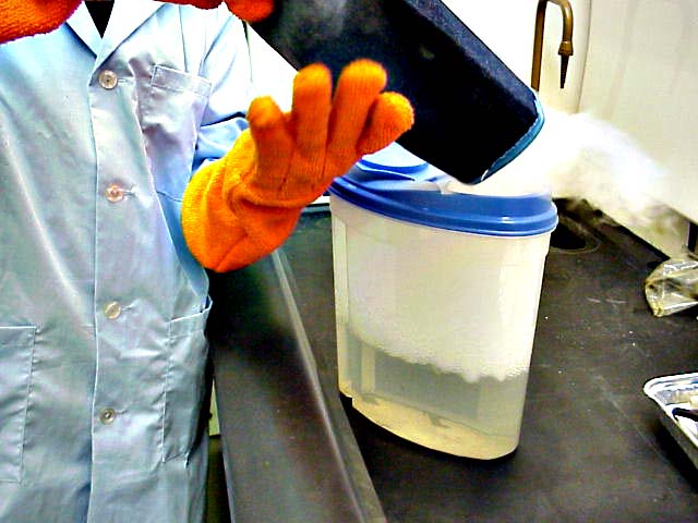
8.
While waiting the 10 minutes, prepare the dry ice - ethanol mixture. You
need to make the dry ice by capturing with a cloth bag the exhaust from
a high pressure CO2 tank that has a siphon (a tube that goes to the bottom,
fluid-filled portion of the tank). Make sure to wear ear protection and
gloves while making the ice. Slowly add the dry ice to approximately two
liters of ethanol. Do it very slowly at the beginning; otherwise, the ethanol
will overflow the container due to rapid evaporation of the dry ice. Keep
adding dry ice until the ethanol is cooled to c. -70 degrees C (which is
the eutectic point of the mixture) and some dry ice remains in the mixture.
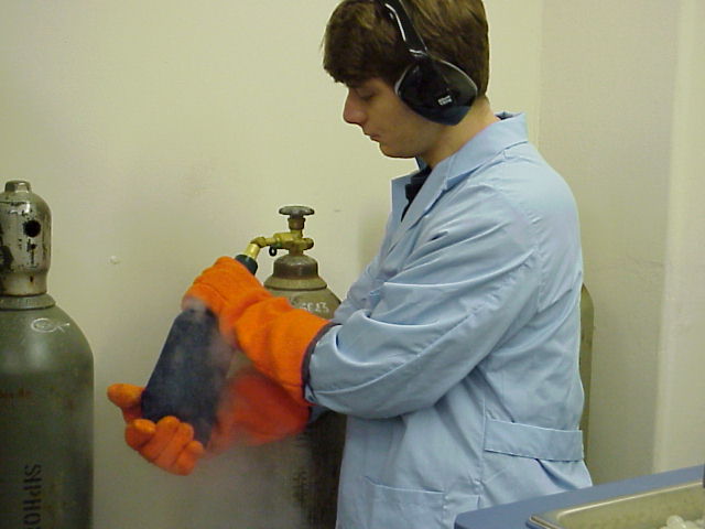 |
Making dry ice by allowing liquid CO2 from a supply tank to expand and freeze in a cloth bag. |
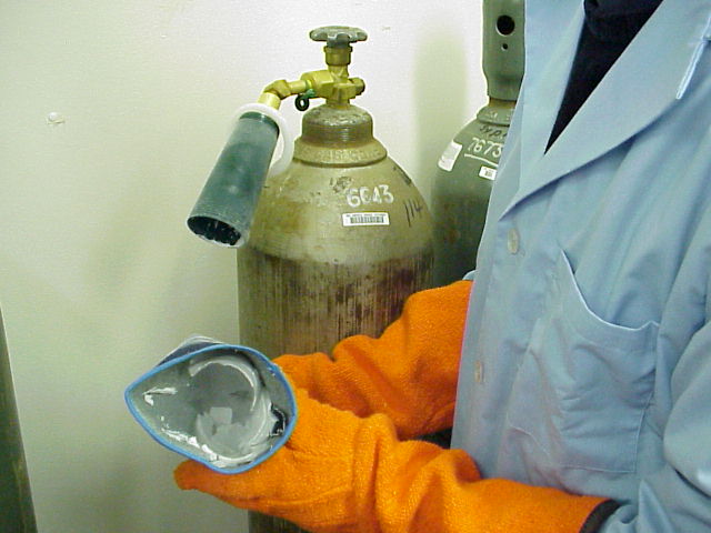 |
Dry ice in the cloth bag. |
 |
Placing dry ice in alcohol and allowing mixture to equilibrate to -70 degrees C. |
9. After the 10 minute transfer time is finished, add more LN into the first cooling tray so that the liquid nitrogen level is approximately 1 to 2 cm above the previous high level.
10. Close valve 3.
11. Open valve 2 for the first line and record the gas pressure of the line. This gas is comprised of the noncondensable phases (e.g., nitrogen, argon, helium).
12. Open valve 3 and close valve 1 of the sample vessel. Wait for a good vacuum.
13. Close valve 2 and then close valve 3.
14. Repeat the procedure for each line.
15. When complete, open valve 3 and check to make sure that all the valves 1 and 2 are closed.
16. Fill the second cooling tray with LN until the liquid covers approximately one centimeter of all the cut-off tubes.
17.
Remove the rubber stopper from the first cooling tray, open the ball valve,
and drain the LN into a dewar. Close the ball valve of the cooling tray
(This might not be possible if some water was in the ball valve prior to
the addition of the LN. In this case, put the rubber stopper back into
the discharge hole.)
 |
Draining the liquid nitrogen from the cooling tray that holds the U-shaped section of the extraction line. |
18. Immediately pour the dry ice - ethanol mixture into the first cooling tray.
19. Within approximately 30 seconds, you should see a white CO2 condensate form in the cut-off tubes. Add more LN into the second cooling tray so that the liquid level is approximately 1 cm above the condensate.
20. Wait approximately 5 to 10 minutes in order to insure complete transfer of the CO2 from the U-tubes to the cut-off tubes.
21. While you are waiting, open the valves to the natural gas line and the oxygen high pressure tank. Bleed the gas through the torch by opening the two small valves on the torch for approximately 15 seconds in order to clear the plastic tubing of atmosphere gas. (Until the tubing is filled with relatively pure natural gas and oxygen, the torch will not light or burn very well). Close the small valves on the torch and wait approximately 30 seconds to allow the natural gas and oxygen to dissipate in the room (we don't want the room to explode!).
22. Partly open the natural gas valve on the torch and light. Increase the flow of natural gas and then slowly open the torch's valve for the oxygen. You will have to adjust the relative mixtures of the natural gas and oxygen until you get a blue flame that is approximately 1 to 2 cm in length and contains little to no yellow color. The torch is now ready for melting the glass tubing.
23. Add enough LN to the cooling tray to have the liquid level approximately 1 to 2 cm above the previous high level.
24. Open valve 2 of the first line and wait approximately five to ten seconds in order to get rid of any remaining noncondensables. Close valve 2. Repeat the procedure for all the lines.
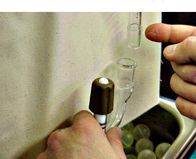
25.
Now you are ready to cut off the tubes. Make sure you are wearing the proper
eye protection to protect you from the UV radiation and from potentially
exploding glass! One at a time, heat uniformly a 1 to 2 cm long stretch
of the glass tubing approximately 2 to 3 cm below the black pressure cap
(the caps are plastic and will melt if touched by the flame). Keep the
flame horizontal in order to not heat the black cap. Try to heat evenly
the front and sides of the tube in this stretch of tubing. As the tubing
starts to collapse, localize the heating within a narrower 0.5 to 1 cm
stretch of the tube. Keep evenly heating the front and sides of the tube.
The tube will continue to collapse and become soft in this region. Gently
grasp the tube below the zone of heating with large tweezers and gently
rotate the tubing in a horizontal plane in order to help the tube to seal
itself. Slowly and gently pull the tube away from the glass line while
you continue heating the glass. The glass tubing will eventually separate
and the tube should be sealed. Lay the tube on the table. Be careful at
this point because if the line had leaked during the extraction process,
then the tube can explode violently within 1 to 10 seconds of removing
it from the liquid nitrogen due to the rapid expansion of gas in the tube.
This happens infrequently; but when it does occur, it is dangerous because
it sends glass shards through the air.
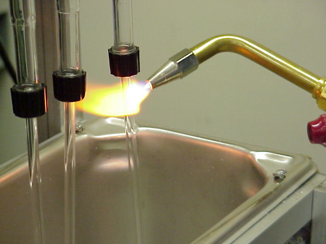 |
Using blow torch to cut off the final CO2 sample vial. |
|
MPEG movie showing how the vial is removed with the
blowtorch
(WARNING: 1.4 Mb file!) |
26. Repeat this procedure for all the cut-off tubes.
27. Close the oxygen (first) and then the natural gas valves on the torch. Then turn off the main valve of the oxygen tank and the main valve of the natural gas line.
28. Remove the rubber stopper of the second cooling tray and open the ball valve in order to drain the LN into a dewar for storage. Leave the bottom valve open.
29. Open all valves 2 and make sure valve 3 is open.
30. Remove the rubber stopper from the first cooling tray and drain the ethanol into a container by opening the ball valve. Leave this valve open. (Be careful at this time because the glass line might rupture if any of the lines leaked during the extraction!)
Preparing the line for a new set of extractions:
1. Wait until the glass line is warmed up to room temperature.
2. Turn on an oven to c. 110 to 150 degrees C in preparation of drying the cleaned sample chambers.
3. Close valve 3, turn vacuum gauge off, and gently remove the sample chambers from the line at the glass connections.
4. Open valve 1 of all the sample chambers and then unscrew the black screw caps by holding on to the glassware immediately above the black cap. Do not put pressure on the glass "arm" during this process. If you can not open the chamber using this technique, then gently rotate and remove the cylindrical glass chamber that held the powder and acid. Remove the O-ring and put in a clean place free of dirt or lint.
5. Flush each sample chamber under the faucet with high pressure, hot water (as hot as possible). Make sure to wear thick rubber gloves during this process in order to protect your hands from the acid and hot water.
6. Rinse each chamber with distilled water in order to minimize the amount of mineral deposit that will form on the glassware during drying.
7. Place the sample chambers (only the glassware that held the powder and acid; NOT the portion of glassware that have the valves) in the oven and wait until they are dry (c. 10 to 20 minutes). You are now ready to load new samples for the next set of extractions.
Updated 13 April 2000