Location
Location ANSS
The ANSS event ID is nc75458907 and the event page is at
https://earthquake.usgs.gov/earthquakes/eventpage/nc75458907/executive.
2026/10/28 12:01:11 39.500 -122.952 10.6 4.0 California
Focal Mechanism
 USGS/SLU Moment Tensor Solution
 ENS  2026/10/28 12:01:11.0  39.50 -122.95  10.6 4.0 California

 Stations used:
   BK.ADAM BK.ATP BK.AUSC BK.BARR BK.BEVN BK.BIGM BK.BJES
   BK.BONV BK.BRIC BK.BUCI BK.DLIK BK.ETSL BK.GASB BK.GRPK
   BK.GTSB BK.GUMB BK.HALS BK.HAYF BK.HOPS BK.HRCH BK.HUNT
   BK.LCOS BK.MCCM BK.MLKN BK.MNRC BK.MORK BK.OAKV BK.ORRS
   BK.PETY BK.PWOD BK.QRDG BK.RBOW BK.RVIT BK.SCOT BK.SHWD
   BK.SNCR BK.SPAN BK.SPRL BK.USAL BK.VAK BK.WTWN NC.GCVB
   NC.GDXB NC.GHGB NC.GRT NC.GSR NC.GSX NC.GTK NC.GWW NC.KCPC
   NC.KNR NC.KRP NC.KTJ NC.KZE NC.NAPC NC.NBPB NC.NCO NC.NTO
   NC.NTOM NC.NTR NC.NTYB

 Filtering commands used:
   cut o DIST/3.3 -40 o DIST/3.3 +50
   rtr
   taper w 0.1
   hp c 0.03 n 3
   lp c 0.10 n 3

 Best Fitting Double Couple
  Mo = 1.45e+22 dyne-cm
  Mw = 4.04
  Z  = 14 km
  Plane   Strike  Dip  Rake
   NP1      337    80   -170
   NP2      245    80   -10
  Principal Axes:
   Axis    Value   Plunge  Azimuth
    T   1.45e+22      0     111
    N   0.00e+00     76      20
    P  -1.45e+22     14     201

 Moment Tensor: (dyne-cm)
    Component   Value
       Mxx    -1.00e+22
       Mxy    -9.34e+21
       Mxz     3.18e+21
       Myy     1.09e+22
       Myz     1.24e+21
       Mzz    -8.58e+20


                     --------------
                 ####------------------
              ########--------------------
             ###########-------------------
           ##############--------------------
          ################--------------------
         ##################-----------------###
        ####################---------###########
        #####################---################
       #####################--###################
       #################------###################
       ##############----------##################
       ##########---------------#################
        ######-------------------#############
        ####---------------------############# T
         #------------------------############
          ------------------------############
           ------------------------##########
             ----------------------########
              ------   -------------######
                 --- P -------------###
                       ------------


 Global CMT Convention Moment Tensor:
      R          T          P
 -8.58e+20   3.18e+21  -1.24e+21
  3.18e+21  -1.00e+22   9.34e+21
 -1.24e+21   9.34e+21   1.09e+22


Details of the solution is found at

http://www.eas.slu.edu/eqc/eqc_mt/MECH.NA/20261028120111/index.html
|
Preferred Solution
The preferred solution from an analysis of the surface-wave spectral amplitude radiation pattern, waveform inversion or first motion observations is
      STK = 245
      DIP = 80
     RAKE = -10
       MW = 4.04
       HS = 14.0
The NDK file is 20261028120111.ndk
The waveform inversion is preferred.
Moment Tensor Comparison
The following compares this source inversion to those provided by others. The purpose is to look for major differences and also to note slight differences that might be inherent to the processing procedure. For completeness the USGS/SLU solution is repeated from above.
| SLU |
UCB |
 USGS/SLU Moment Tensor Solution
 ENS  2026/10/28 12:01:11.0  39.50 -122.95  10.6 4.0 California

 Stations used:
   BK.ADAM BK.ATP BK.AUSC BK.BARR BK.BEVN BK.BIGM BK.BJES
   BK.BONV BK.BRIC BK.BUCI BK.DLIK BK.ETSL BK.GASB BK.GRPK
   BK.GTSB BK.GUMB BK.HALS BK.HAYF BK.HOPS BK.HRCH BK.HUNT
   BK.LCOS BK.MCCM BK.MLKN BK.MNRC BK.MORK BK.OAKV BK.ORRS
   BK.PETY BK.PWOD BK.QRDG BK.RBOW BK.RVIT BK.SCOT BK.SHWD
   BK.SNCR BK.SPAN BK.SPRL BK.USAL BK.VAK BK.WTWN NC.GCVB
   NC.GDXB NC.GHGB NC.GRT NC.GSR NC.GSX NC.GTK NC.GWW NC.KCPC
   NC.KNR NC.KRP NC.KTJ NC.KZE NC.NAPC NC.NBPB NC.NCO NC.NTO
   NC.NTOM NC.NTR NC.NTYB

 Filtering commands used:
   cut o DIST/3.3 -40 o DIST/3.3 +50
   rtr
   taper w 0.1
   hp c 0.03 n 3
   lp c 0.10 n 3

 Best Fitting Double Couple
  Mo = 1.45e+22 dyne-cm
  Mw = 4.04
  Z  = 14 km
  Plane   Strike  Dip  Rake
   NP1      337    80   -170
   NP2      245    80   -10
  Principal Axes:
   Axis    Value   Plunge  Azimuth
    T   1.45e+22      0     111
    N   0.00e+00     76      20
    P  -1.45e+22     14     201

 Moment Tensor: (dyne-cm)
    Component   Value
       Mxx    -1.00e+22
       Mxy    -9.34e+21
       Mxz     3.18e+21
       Myy     1.09e+22
       Myz     1.24e+21
       Mzz    -8.58e+20


                     --------------
                 ####------------------
              ########--------------------
             ###########-------------------
           ##############--------------------
          ################--------------------
         ##################-----------------###
        ####################---------###########
        #####################---################
       #####################--###################
       #################------###################
       ##############----------##################
       ##########---------------#################
        ######-------------------#############
        ####---------------------############# T
         #------------------------############
          ------------------------############
           ------------------------##########
             ----------------------########
              ------   -------------######
                 --- P -------------###
                       ------------


 Global CMT Convention Moment Tensor:
      R          T          P
 -8.58e+20   3.18e+21  -1.24e+21
  3.18e+21  -1.00e+22   9.34e+21
 -1.24e+21   9.34e+21   1.09e+22


Details of the solution is found at

http://www.eas.slu.edu/eqc/eqc_mt/MECH.NA/20261028120111/index.html
|
Moment Tensor (Mw)
Moment 1.278e+15 N-m
Magnitude 4.00 Mw
Depth 14.0 km
Percent DC 80%
Half Duration -
Catalog NC
Data Source NC
Contributor NC
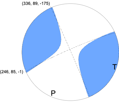
Nodal Planes
Plane	Strike	Dip	Rake
NP1	246	85	-1
NP2	336	89	-175
Principal Axes
Axis	Value	Plunge	Azimuth
T	1.340e+15	3	111
N	-0.135e+15	85	347
P	-1.205e+15	4	202
|
Magnitudes
Given the availability of digital waveforms for determination of the moment tensor, this section documents the added processing leading to mLg, if appropriate to the region, and ML by application of the respective IASPEI formulae. As a research study, the linear distance term of the IASPEI formula
for ML is adjusted to remove a linear distance trend in residuals to give a regionally defined ML. The defined ML uses horizontal component recordings, but the same procedure is applied to the vertical components since there may be some interest in vertical component ground motions. Residual plots versus distance may indicate interesting features of ground motion scaling in some distance ranges. A residual plot of the regionalized magnitude is given as a function of distance and azimuth, since data sets may transcend different wave propagation provinces.
ML Magnitude
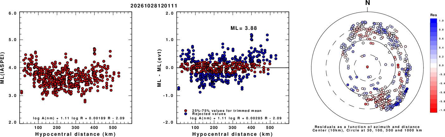
Left: ML computed using the IASPEI formula for Horizontal components. Center: ML residuals computed using a modified IASPEI formula that accounts for path specific attenuation; the values used for the trimmed mean are indicated. The ML relation used for each figure is given at the bottom of each plot.
Right: Residuals from new relation as a function of distance and azimuth.
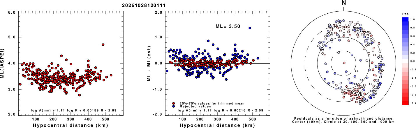
Left: ML computed using the IASPEI formula for Vertical components (research). Center: ML residuals computed using a modified IASPEI formula that accounts for path specific attenuation; the values used for the trimmed mean are indicated. The ML relation used for each figure is given at the bottom of each plot.
Right: Residuals from new relation as a function of distance and azimuth.
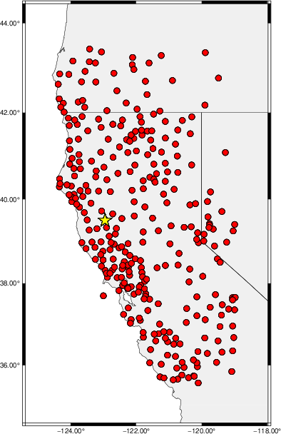
Map showing station locations used for computing the ML's. No distinction is made whether the vertical (Z) or horizontal (H) components were used.
Context
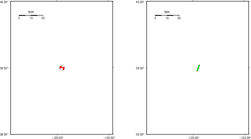
The left panel of the next figure presents the focal mechanism for this earthquake (red) in the context of other nearby events (blue) in the SLU Moment Tensor Catalog. The right panel shows the inferred direction of maximum compressive stress and the type of faulting (green is strike-slip, red is normal, blue is thrust; oblique is shown by a combination of colors). Thus context plot is useful for assessing the appropriateness of the moment tensor of this event.
Waveform Inversion using wvfgrd96
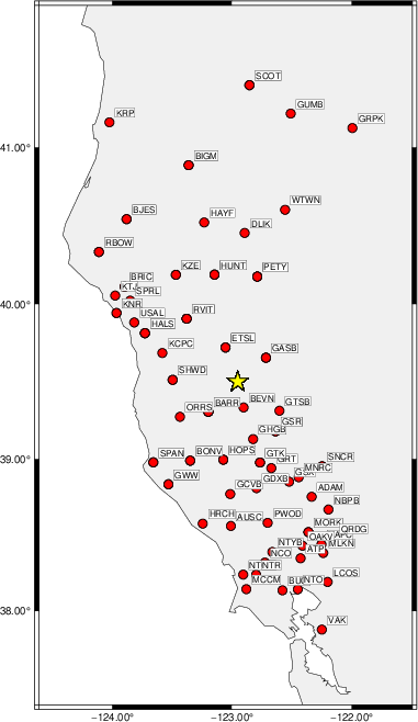
The focal mechanism was determined using broadband seismic waveforms. The location of the event (star) and the
stations used for (red) the waveform inversion are shown in the next figure.
|
|
Location of broadband stations used for waveform inversion
|
The program wvfgrd96 was used with good traces observed at short distance to determine the focal mechanism, depth and seismic moment. This technique requires a high quality signal and well determined velocity model for the Green's functions. To the extent that these are the quality data, this type of mechanism should be preferred over the radiation pattern technique which requires the separate step of defining the pressure and tension quadrants and the correct strike.
The observed and predicted traces are filtered using the following gsac commands:
cut o DIST/3.3 -40 o DIST/3.3 +50
rtr
taper w 0.1
hp c 0.03 n 3
lp c 0.10 n 3
The results of this grid search are as follow:
           DEPTH  STK   DIP  RAKE   MW    FIT
WVFGRD96    1.0   245    90     0   3.41 0.2083
WVFGRD96    2.0   245    85    -5   3.58 0.3194
WVFGRD96    3.0   245    85     5   3.65 0.3665
WVFGRD96    4.0   245    85    20   3.71 0.4062
WVFGRD96    5.0   245    85    25   3.77 0.4444
WVFGRD96    6.0   245    90   -25   3.81 0.4862
WVFGRD96    7.0   245    90   -20   3.85 0.5246
WVFGRD96    8.0    65    90    25   3.90 0.5623
WVFGRD96    9.0   245    90   -25   3.93 0.5887
WVFGRD96   10.0   245    80   -20   3.96 0.6113
WVFGRD96   11.0   245    80   -15   3.98 0.6302
WVFGRD96   12.0   245    80   -15   4.01 0.6436
WVFGRD96   13.0   245    80   -15   4.02 0.6516
WVFGRD96   14.0   245    80   -10   4.04 0.6555
WVFGRD96   15.0   245    80   -10   4.06 0.6552
WVFGRD96   16.0   245    80   -10   4.07 0.6521
WVFGRD96   17.0   245    80   -10   4.08 0.6451
WVFGRD96   18.0   245    80   -10   4.09 0.6360
WVFGRD96   19.0   245    85   -10   4.10 0.6247
WVFGRD96   20.0   245    85   -10   4.11 0.6114
WVFGRD96   21.0   245    80   -10   4.12 0.5972
WVFGRD96   22.0   245    85   -10   4.12 0.5822
WVFGRD96   23.0   245    85   -10   4.12 0.5662
WVFGRD96   24.0   245    90   -15   4.13 0.5495
WVFGRD96   25.0   245    90   -15   4.13 0.5335
WVFGRD96   26.0   245    90   -15   4.13 0.5174
WVFGRD96   27.0   245    85   -15   4.13 0.5015
WVFGRD96   28.0   245    85   -15   4.13 0.4868
WVFGRD96   29.0   245    85   -15   4.13 0.4721
The best solution is
WVFGRD96 14.0 245 80 -10 4.04 0.6555
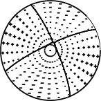
The mechanism corresponding to the best fit is
|
|
Figure 1. Waveform inversion focal mechanism
|
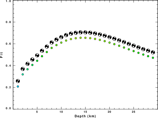
The best fit as a function of depth is given in the following figure:
|
|
Figure 2. Depth sensitivity for waveform mechanism
|
The comparison of the observed and predicted waveforms is given in the next figure. The red traces are the observed and the blue are the predicted.
Each observed-predicted component is plotted to the same scale and peak amplitudes are indicated by the numbers to the left of each trace. A pair of numbers is given in black at the right of each predicted traces. The upper number it the time shift required for maximum correlation between the observed and predicted traces. This time shift is required because the synthetics are not computed at exactly the same distance as the observed, the velocity model used in the predictions may not be perfect and the epicentral parameters may be be off.
A positive time shift indicates that the prediction is too fast and should be delayed to match the observed trace (shift to the right in this figure). A negative value indicates that the prediction is too slow. The lower number gives the percentage of variance reduction to characterize the individual goodness of fit (100% indicates a perfect fit).
The bandpass filter used in the processing and for the display was
cut o DIST/3.3 -40 o DIST/3.3 +50
rtr
taper w 0.1
hp c 0.03 n 3
lp c 0.10 n 3

|
|
Figure 3. Waveform comparison for selected depth. Red: observed; Blue - predicted. The time shift with respect to the model prediction is indicated. The percent of fit is also indicated. The time scale is relative to the first trace sample.
|
|
|
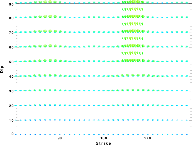
Focal mechanism sensitivity at the preferred depth. The red color indicates a very good fit to the waveforms.
Each solution is plotted as a vector at a given value of strike and dip with the angle of the vector representing the rake angle, measured, with respect to the upward vertical (N) in the figure.
|
A check on the assumed source location is possible by looking at the time shifts between the observed and predicted traces. The time shifts for waveform matching arise for several reasons:
- The origin time and epicentral distance are incorrect
- The velocity model used for the inversion is incorrect
- The velocity model used to define the P-arrival time is not the
same as the velocity model used for the waveform inversion
(assuming that the initial trace alignment is based on the
P arrival time)
Assuming only a mislocation, the time shifts are fit to a functional form:
Time_shift = A + B cos Azimuth + C Sin Azimuth
The time shifts for this inversion lead to the next figure:
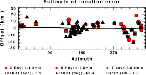
The derived shift in origin time and epicentral coordinates are given at the bottom of the figure.
Velocity Model
The WUS.model used for the waveform synthetic seismograms and for the surface wave eigenfunctions and dispersion is as follows
(The format is in the model96 format of Computer Programs in Seismology).
MODEL.01
Model after     8 iterations
ISOTROPIC
KGS
FLAT EARTH
1-D
CONSTANT VELOCITY
LINE08
LINE09
LINE10
LINE11
      H(KM)   VP(KM/S)   VS(KM/S) RHO(GM/CC)         QP         QS       ETAP       ETAS      FREFP      FREFS
     1.9000     3.4065     2.0089     2.2150  0.302E-02  0.679E-02   0.00       0.00       1.00       1.00
     6.1000     5.5445     3.2953     2.6089  0.349E-02  0.784E-02   0.00       0.00       1.00       1.00
    13.0000     6.2708     3.7396     2.7812  0.212E-02  0.476E-02   0.00       0.00       1.00       1.00
    19.0000     6.4075     3.7680     2.8223  0.111E-02  0.249E-02   0.00       0.00       1.00       1.00
     0.0000     7.9000     4.6200     3.2760  0.164E-10  0.370E-10   0.00       0.00       1.00       1.00
Last Changed Wed Oct 28 09:11:30 CDT 2026