Location
Location ANSS
The ANSS event ID is tx2026usvdxs and the event page is at
https://earthquake.usgs.gov/earthquakes/eventpage/tx2026usvdxs/executive.
2026/10/21 12:45:57 31.654 -104.139 6.1 3.7 Texas
Focal Mechanism
 USGS/SLU Moment Tensor Solution
 ENS  2026/10/21 12:45:57.0  31.65 -104.14   6.1 3.7 Texas

 Stations used:
   4O.BP01 4O.CT01 4O.CT02 4O.CV01 4O.DB03 4O.DB04 4O.LWM1
   4O.LWM2 4O.NGL01 4O.NGL03 4O.PL01 4O.SA02 4O.SA04 4O.VW01
   4O.WB02 4O.WB04 4O.WB05 4O.WB09 4O.WB11 4O.WB12 4O.WB15
   4O.WB16 4O.WB21 4O.WB22 4O.WB25 4O.WW01 4O.WW02 4T.NM01
   4T.NM02 TX.MNHN TX.PB01 TX.PB03 TX.PB04 TX.PB05 TX.PB06
   TX.PB07 TX.PB08 TX.PB10 TX.PB11 TX.PB12 TX.PB13 TX.PB14
   TX.PB16 TX.PB18 TX.PB19 TX.PB21 TX.PB24 TX.PB28 TX.PB29
   TX.PB31 TX.PB33 TX.PB35 TX.PB36 TX.PB38 TX.PB39 TX.PB40
   TX.PB44 TX.PB46 TX.PB47 TX.PB51 TX.PB54 TX.PCOS TX.PECS
   TX.VHRN

 Filtering commands used:
   cut o DIST/3.3 -10 o DIST/3.3 +50
   rtr
   taper w 0.1
   hp c 0.05 n 3
   lp c 0.15 n 3

 Best Fitting Double Couple
  Mo = 2.66e+21 dyne-cm
  Mw = 3.55
  Z  = 6 km
  Plane   Strike  Dip  Rake
   NP1       54    66   -116
   NP2      285    35   -45
  Principal Axes:
   Axis    Value   Plunge  Azimuth
    T   2.66e+21     17     163
    N   0.00e+00     24      66
    P  -2.66e+21     60     285

 Moment Tensor: (dyne-cm)
    Component   Value
       Mxx     2.19e+21
       Mxy    -4.93e+20
       Mxz    -1.02e+21
       Myy    -4.21e+20
       Myz     1.32e+21
       Mzz    -1.77e+21


                     ##############
                 ######################
              ############################
             ##########----################
           #####-------------------##########
          ###-------------------------######--
         #-------------------------------###---
        #---------------------------------------
        -----------   -------------------###----
       ------------ P ------------------#####----
       ------------   ----------------########---
       -----------------------------###########--
       ---------------------------##############-
        ------------------------################
        ---------------------###################
         -----------------#####################
          ------------########################
           ----##############################
             ##############################
              #################   ########
                 ############## T #####
                     ##########   #


 Global CMT Convention Moment Tensor:
      R          T          P
 -1.77e+21  -1.02e+21  -1.32e+21
 -1.02e+21   2.19e+21   4.93e+20
 -1.32e+21   4.93e+20  -4.21e+20


Details of the solution is found at

http://www.eas.slu.edu/eqc/eqc_mt/MECH.NA/20261021124557/index.html
|
Preferred Solution
The preferred solution from an analysis of the surface-wave spectral amplitude radiation pattern, waveform inversion or first motion observations is
      STK = 285
      DIP = 35
     RAKE = -45
       MW = 3.55
       HS = 6.0
The NDK file is 20261021124557.ndk
The waveform inversion is preferred.
Moment Tensor Comparison
The following compares this source inversion to those provided by others. The purpose is to look for major differences and also to note slight differences that might be inherent to the processing procedure. For completeness the USGS/SLU solution is repeated from above.
| SLU |
USGSMWR |
 USGS/SLU Moment Tensor Solution
 ENS  2026/10/21 12:45:57.0  31.65 -104.14   6.1 3.7 Texas

 Stations used:
   4O.BP01 4O.CT01 4O.CT02 4O.CV01 4O.DB03 4O.DB04 4O.LWM1
   4O.LWM2 4O.NGL01 4O.NGL03 4O.PL01 4O.SA02 4O.SA04 4O.VW01
   4O.WB02 4O.WB04 4O.WB05 4O.WB09 4O.WB11 4O.WB12 4O.WB15
   4O.WB16 4O.WB21 4O.WB22 4O.WB25 4O.WW01 4O.WW02 4T.NM01
   4T.NM02 TX.MNHN TX.PB01 TX.PB03 TX.PB04 TX.PB05 TX.PB06
   TX.PB07 TX.PB08 TX.PB10 TX.PB11 TX.PB12 TX.PB13 TX.PB14
   TX.PB16 TX.PB18 TX.PB19 TX.PB21 TX.PB24 TX.PB28 TX.PB29
   TX.PB31 TX.PB33 TX.PB35 TX.PB36 TX.PB38 TX.PB39 TX.PB40
   TX.PB44 TX.PB46 TX.PB47 TX.PB51 TX.PB54 TX.PCOS TX.PECS
   TX.VHRN

 Filtering commands used:
   cut o DIST/3.3 -10 o DIST/3.3 +50
   rtr
   taper w 0.1
   hp c 0.05 n 3
   lp c 0.15 n 3

 Best Fitting Double Couple
  Mo = 2.66e+21 dyne-cm
  Mw = 3.55
  Z  = 6 km
  Plane   Strike  Dip  Rake
   NP1       54    66   -116
   NP2      285    35   -45
  Principal Axes:
   Axis    Value   Plunge  Azimuth
    T   2.66e+21     17     163
    N   0.00e+00     24      66
    P  -2.66e+21     60     285

 Moment Tensor: (dyne-cm)
    Component   Value
       Mxx     2.19e+21
       Mxy    -4.93e+20
       Mxz    -1.02e+21
       Myy    -4.21e+20
       Myz     1.32e+21
       Mzz    -1.77e+21


                     ##############
                 ######################
              ############################
             ##########----################
           #####-------------------##########
          ###-------------------------######--
         #-------------------------------###---
        #---------------------------------------
        -----------   -------------------###----
       ------------ P ------------------#####----
       ------------   ----------------########---
       -----------------------------###########--
       ---------------------------##############-
        ------------------------################
        ---------------------###################
         -----------------#####################
          ------------########################
           ----##############################
             ##############################
              #################   ########
                 ############## T #####
                     ##########   #


 Global CMT Convention Moment Tensor:
      R          T          P
 -1.77e+21  -1.02e+21  -1.32e+21
 -1.02e+21   2.19e+21   4.93e+20
 -1.32e+21   4.93e+20  -4.21e+20


Details of the solution is found at

http://www.eas.slu.edu/eqc/eqc_mt/MECH.NA/20261021124557/index.html
|
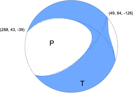
Regional Moment Tensor (Mwr)
Moment 2.946e+14 N-m
Magnitude 3.58 Mwr
Depth 5.0 km
Percent DC 81%
Half Duration -
Catalog US
Data Source US
Contributor US
Nodal Planes
Plane	Strike	Dip	Rake
NP1	288	43	-39
NP2	49	64	-126
Principal Axes
Axis	Value	Plunge	Azimuth
T	2.790e+14	12	164
N	0.290e+14	32	67
P	-3.080e+14	55	273
|
Magnitudes
Given the availability of digital waveforms for determination of the moment tensor, this section documents the added processing leading to mLg, if appropriate to the region, and ML by application of the respective IASPEI formulae. As a research study, the linear distance term of the IASPEI formula
for ML is adjusted to remove a linear distance trend in residuals to give a regionally defined ML. The defined ML uses horizontal component recordings, but the same procedure is applied to the vertical components since there may be some interest in vertical component ground motions. Residual plots versus distance may indicate interesting features of ground motion scaling in some distance ranges. A residual plot of the regionalized magnitude is given as a function of distance and azimuth, since data sets may transcend different wave propagation provinces.
mb_Lg Magnitude
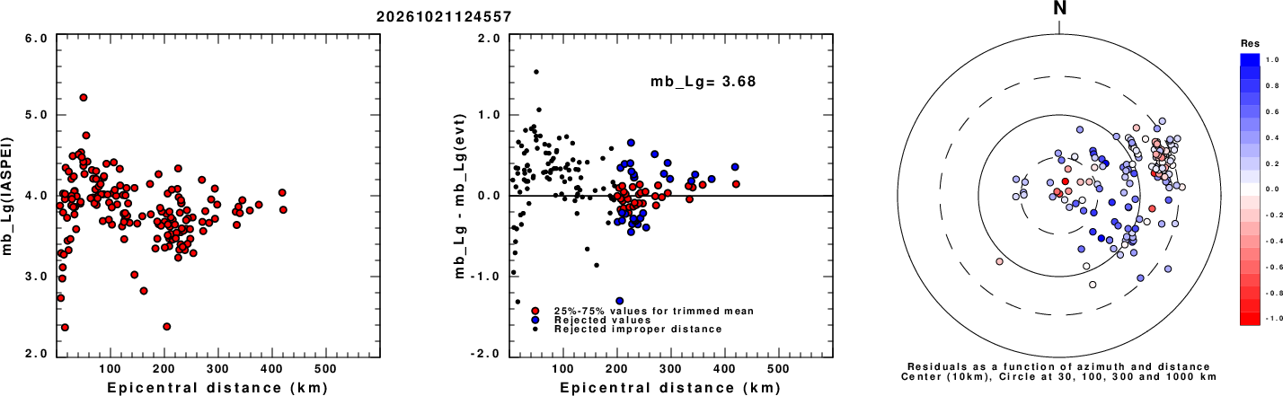
Left: mb_Lg computed using the IASPEI formula. Center: mb_Lg residuals versus epicentral distance ; the values used for the trimmed mean magnitude estimate are indicated.
Right: residuals as a function of distance and azimuth.
ML Magnitude
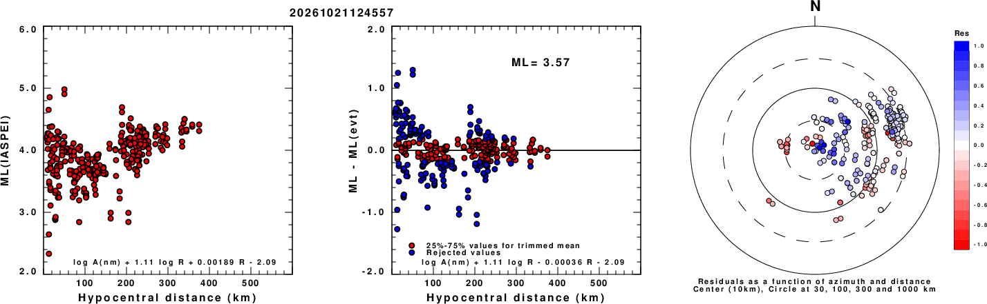
Left: ML computed using the IASPEI formula for Horizontal components. Center: ML residuals computed using a modified IASPEI formula that accounts for path specific attenuation; the values used for the trimmed mean are indicated. The ML relation used for each figure is given at the bottom of each plot.
Right: Residuals from new relation as a function of distance and azimuth.
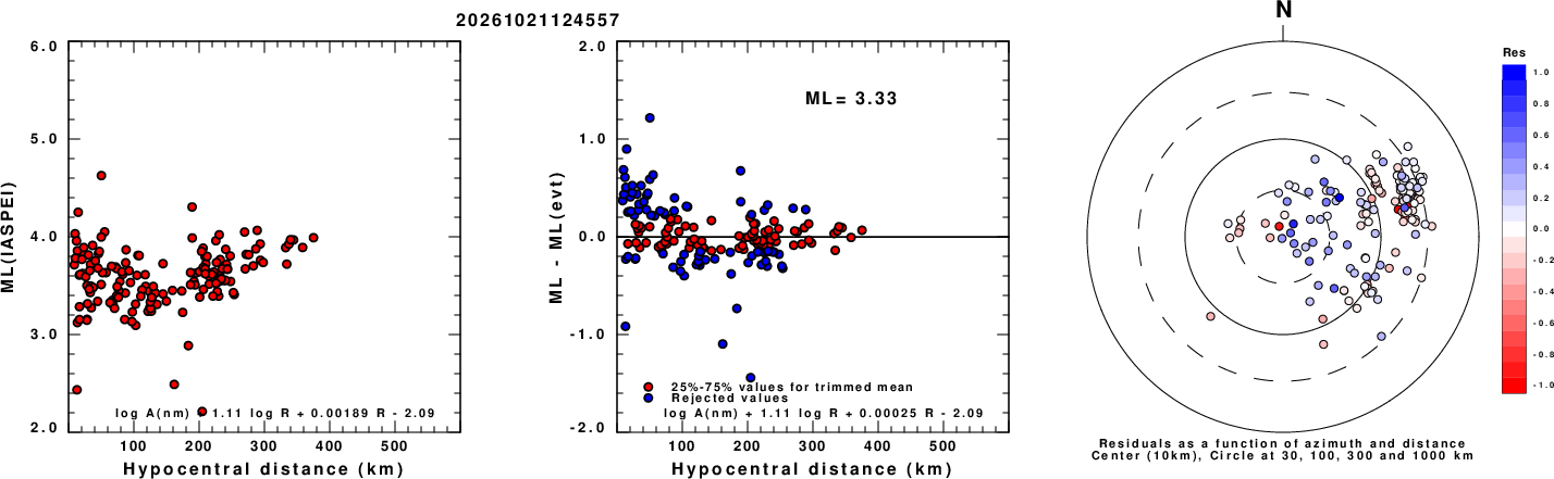
Left: ML computed using the IASPEI formula for Vertical components (research). Center: ML residuals computed using a modified IASPEI formula that accounts for path specific attenuation; the values used for the trimmed mean are indicated. The ML relation used for each figure is given at the bottom of each plot.
Right: Residuals from new relation as a function of distance and azimuth.
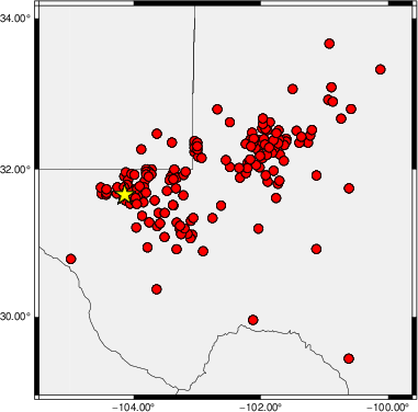
Map showing station locations used for computing the ML's. No distinction is made whether the vertical (Z) or horizontal (H) components were used.
Context
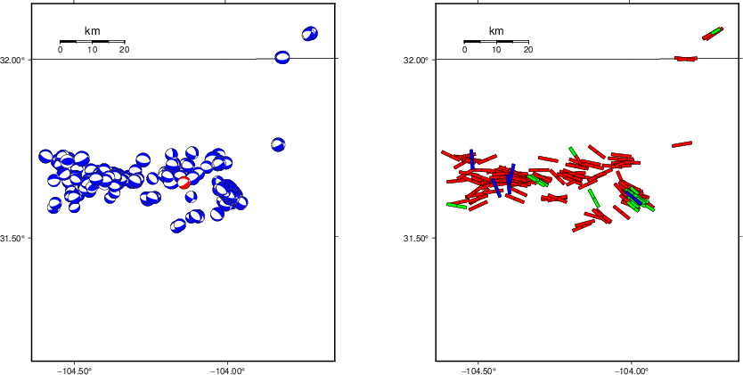
The left panel of the next figure presents the focal mechanism for this earthquake (red) in the context of other nearby events (blue) in the SLU Moment Tensor Catalog. The right panel shows the inferred direction of maximum compressive stress and the type of faulting (green is strike-slip, red is normal, blue is thrust; oblique is shown by a combination of colors). Thus context plot is useful for assessing the appropriateness of the moment tensor of this event.
Waveform Inversion using wvfgrd96
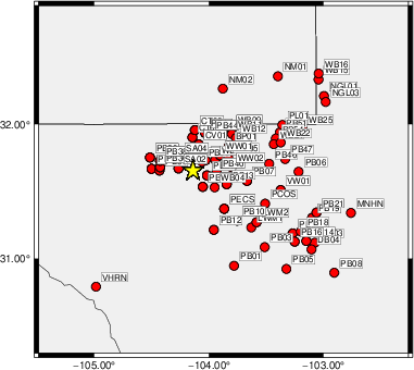
The focal mechanism was determined using broadband seismic waveforms. The location of the event (star) and the
stations used for (red) the waveform inversion are shown in the next figure.
|
|
Location of broadband stations used for waveform inversion
|
The program wvfgrd96 was used with good traces observed at short distance to determine the focal mechanism, depth and seismic moment. This technique requires a high quality signal and well determined velocity model for the Green's functions. To the extent that these are the quality data, this type of mechanism should be preferred over the radiation pattern technique which requires the separate step of defining the pressure and tension quadrants and the correct strike.
The observed and predicted traces are filtered using the following gsac commands:
cut o DIST/3.3 -10 o DIST/3.3 +50
rtr
taper w 0.1
hp c 0.05 n 3
lp c 0.15 n 3
The results of this grid search are as follow:
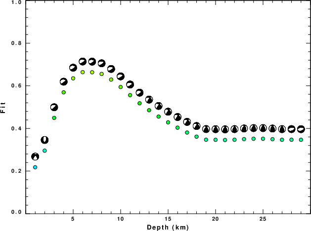
           DEPTH  STK   DIP  RAKE   MW    FIT
WVFGRD96    1.0   220    70   -35   3.07 0.2181
WVFGRD96    2.0    25    50   -60   3.32 0.2957
WVFGRD96    3.0   290    25   -30   3.43 0.4494
WVFGRD96    4.0   285    30   -40   3.48 0.5693
WVFGRD96    5.0   285    35   -45   3.52 0.6349
WVFGRD96    6.0   285    35   -45   3.55 0.6639
WVFGRD96    7.0   285    40   -45   3.57 0.6634
WVFGRD96    8.0   280    35   -50   3.66 0.6555
WVFGRD96    9.0   285    35   -45   3.67 0.6291
WVFGRD96   10.0   285    35   -45   3.68 0.5943
WVFGRD96   11.0   285    40   -45   3.70 0.5561
WVFGRD96   12.0   290    40   -35   3.70 0.5179
WVFGRD96   13.0   310    45    10   3.69 0.4854
WVFGRD96   14.0   310    45    10   3.70 0.4556
WVFGRD96   15.0   310    45    10   3.71 0.4285
WVFGRD96   16.0   310    45    10   3.72 0.4037
WVFGRD96   17.0   310    45    10   3.73 0.3808
WVFGRD96   18.0   315    45    15   3.73 0.3614
WVFGRD96   19.0   330    50    40   3.75 0.3471
WVFGRD96   20.0   330    50    45   3.76 0.3467
WVFGRD96   21.0   335    50    50   3.77 0.3458
WVFGRD96   22.0   335    50    50   3.78 0.3470
WVFGRD96   23.0   340    45    50   3.79 0.3499
WVFGRD96   24.0   340    45    50   3.79 0.3516
WVFGRD96   25.0   335    50    50   3.80 0.3517
WVFGRD96   26.0   335    50    55   3.80 0.3496
WVFGRD96   27.0   335    50    55   3.80 0.3469
WVFGRD96   28.0   260    45   -85   3.84 0.3470
WVFGRD96   29.0   265    45   -80   3.84 0.3467
The best solution is
WVFGRD96 6.0 285 35 -45 3.55 0.6639
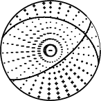
The mechanism corresponding to the best fit is
|
|
Figure 1. Waveform inversion focal mechanism
|
The best fit as a function of depth is given in the following figure:
|
|
Figure 2. Depth sensitivity for waveform mechanism
|
The comparison of the observed and predicted waveforms is given in the next figure. The red traces are the observed and the blue are the predicted.
Each observed-predicted component is plotted to the same scale and peak amplitudes are indicated by the numbers to the left of each trace. A pair of numbers is given in black at the right of each predicted traces. The upper number it the time shift required for maximum correlation between the observed and predicted traces. This time shift is required because the synthetics are not computed at exactly the same distance as the observed, the velocity model used in the predictions may not be perfect and the epicentral parameters may be be off.
A positive time shift indicates that the prediction is too fast and should be delayed to match the observed trace (shift to the right in this figure). A negative value indicates that the prediction is too slow. The lower number gives the percentage of variance reduction to characterize the individual goodness of fit (100% indicates a perfect fit).
The bandpass filter used in the processing and for the display was
cut o DIST/3.3 -10 o DIST/3.3 +50
rtr
taper w 0.1
hp c 0.05 n 3
lp c 0.15 n 3

|
|
Figure 3. Waveform comparison for selected depth. Red: observed; Blue - predicted. The time shift with respect to the model prediction is indicated. The percent of fit is also indicated. The time scale is relative to the first trace sample.
|
|
|
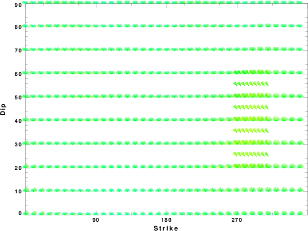
Focal mechanism sensitivity at the preferred depth. The red color indicates a very good fit to the waveforms.
Each solution is plotted as a vector at a given value of strike and dip with the angle of the vector representing the rake angle, measured, with respect to the upward vertical (N) in the figure.
|
A check on the assumed source location is possible by looking at the time shifts between the observed and predicted traces. The time shifts for waveform matching arise for several reasons:
- The origin time and epicentral distance are incorrect
- The velocity model used for the inversion is incorrect
- The velocity model used to define the P-arrival time is not the
same as the velocity model used for the waveform inversion
(assuming that the initial trace alignment is based on the
P arrival time)
Assuming only a mislocation, the time shifts are fit to a functional form:
Time_shift = A + B cos Azimuth + C Sin Azimuth
The time shifts for this inversion lead to the next figure:
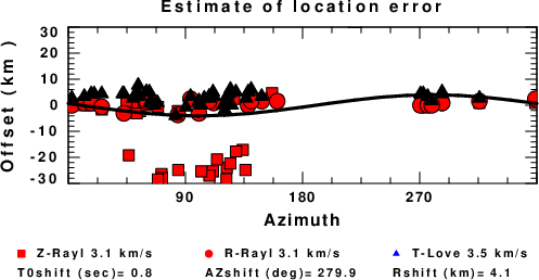
The derived shift in origin time and epicentral coordinates are given at the bottom of the figure.
Velocity Model
The WUS.model used for the waveform synthetic seismograms and for the surface wave eigenfunctions and dispersion is as follows
(The format is in the model96 format of Computer Programs in Seismology).
MODEL.01
Model after     8 iterations
ISOTROPIC
KGS
FLAT EARTH
1-D
CONSTANT VELOCITY
LINE08
LINE09
LINE10
LINE11
      H(KM)   VP(KM/S)   VS(KM/S) RHO(GM/CC)         QP         QS       ETAP       ETAS      FREFP      FREFS
     1.9000     3.4065     2.0089     2.2150  0.302E-02  0.679E-02   0.00       0.00       1.00       1.00
     6.1000     5.5445     3.2953     2.6089  0.349E-02  0.784E-02   0.00       0.00       1.00       1.00
    13.0000     6.2708     3.7396     2.7812  0.212E-02  0.476E-02   0.00       0.00       1.00       1.00
    19.0000     6.4075     3.7680     2.8223  0.111E-02  0.249E-02   0.00       0.00       1.00       1.00
     0.0000     7.9000     4.6200     3.2760  0.164E-10  0.370E-10   0.00       0.00       1.00       1.00
Last Changed Wed Oct 21 10:07:37 CDT 2026